Kia Soul EV: Crash Pad / Main Crash Pad Assembly Repair procedures
Kia Soul EV (PS EV) 2015-2020 Service Manual / Body (Interior and Exterior) / Crash Pad / Main Crash Pad Assembly Repair procedures
| Replacement |
|
|
| 1. |
Disconnect the negative (-) battery terminal. |
| 2. |
Remove both sides of the front pillar trim.
(Refer to Interior Trim - "Front Pillar Trim") |
| 3. |
Remove both sides of the cowl side trim.
(Refer to Interior Trim - "Cowl Side Trim") |
| 4. |
Remove the instrument cluster.
(Refer to Body Electrical System - "Instrument Cluster") |
| 5. |
Remove the crash pad lower panel.
(Refer to Crash Pad - "Crash Pad Lower Panel") |
| 6. |
Remove the glove box housing.
(Refer to Crash Pad - "Glove Box Housing") |
| 7. |
Remove the audio unit or AVN head unit.
(Refer to Body Electrical System - "Audio Unit")
(Refer to Body Electrical System - "AVN Head Unit") |
| 8. |
Remove the crash pad center lower panel.
(Refer to Crash Pad - "Crash Pad Center Panel") |
| 9. |
Remove the steering column shroud lower panel.
(Refer to Crash Pad - "Steering Column Shroud Panel") |
| 10. |
Remove the steering wheel.
(Refer to Steering System - "Steering Wheel") |
| 11. |
Remove the multifunction switch assembly.
(Refer to Body Electrical System - "Multifunction Switch") |
| 12. |
Using a screwdriver or remover, remove the crash pad lower switch panel (A).
|
| 13. |
Disconnect the crash pad lower switch connector (A).
|
| 14. |
Using a screwdriver or remover, remove the crash pad center air vent panel (A).
|
| 15. |
Disconnect the hazard switch connector (A).
|
| 16. |
After loosening the mounting screws, remove the charging notification lamp assembly using a screw driver.
|
| 17. |
Disconnect the charging notification lamp connector (A).
|
| 18. |
Remove the twitter speaker.
|
| 19. |
Using a screwdriver or remover, remove the photo sensor (A). |
| 20. |
Disconnect the photo sensor connector (B).
|
| 21. |
Loosen the mounting bolts (A). |
| 22. |
Disconnect the passenger''s airbag connector (B).
|
| 23. |
Remove the center fascia panel side''s mounting clip (A). |
| 24. |
After loosening the mounting bolts and nuts, remove the main crash pad assembly (B).
|
| 25. |
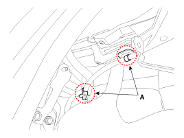
Right before removing the main crash pad, slightly lift the
main crash pad and remove the twitter speaker connector mounting clips
(A) located at both ends.
[LH]
[RH]
|
| 26. |
Install in the reverse order of removal.
|
 Main Crash Pad Assembly Components and Components Location
Component Location
1. Main crash pad assembly
...
 Cowl Cross Bar Assembly Components and Components Location
Component Location
1. Cowl cross bar assembly
...
Other information:
Kia Soul EV (PS EV) 2015-2020 Service Manual: Yaw-rate and Lateral G Sensor Description and Operation
Description The yaw rate and G sensor is included inside the air bag control module (SRSCM). When the vehicle is turning with respect to a vertical axis the yaw rate sensor detects the yaw rate electronically by the vibration change of plate fork inside the yaw rate sensor. If yaw velocity ...
Kia Soul EV (PS EV) 2015-2020 Service Manual: Front Hub / Knuckle Repair procedures
Replacement 1. Loosen the wheel nuts slightly. Raise the vehicle, and make sure it is securely supported. 2. Remove the front wheel and tire (A) from front hub. Tightening torque: 88.3 ~ 107.9 N.m (9.0 ~ 11.0 kgf.m, 65.1 ~ 79.6 lb-ft) Be careful not to da ...
Copyright © www.ksoulev.com 2020-2025


